Product details
Product Overview
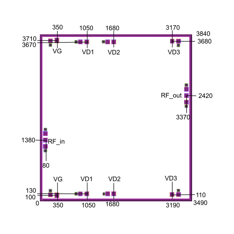
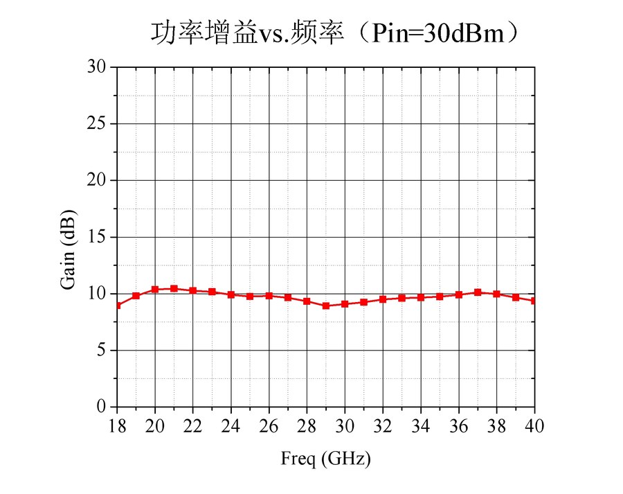
The RFSPA1251C-1840P10 is a GaN power amplifier chip covering 18.0–40.0 GHz, with 10 dB power gain and 40 dBm saturated output power. It operates in both pulsed and CW modes. Chip size: 3.49 × 3.84 × 0.05 mm. All chips are 100% DC and RF tested on-wafer.
Key Features
18.0–40.0 GHz coverage in a compact 3.49 × 3.84 × 0.05 mm die
10 dB power gain with ±1 dB flatness; 20 dB linear gain
40 dBm saturated output power
15% power-added efficiency (PAE)
Operates in both pulsed and CW modes
100% DC and RF tested on-wafer; broadband ridge-waveguide package and diamond carrier assembly recommended for reduced loss and junction temperature
Technical Specifications
| Model | RFSPA1251C-1840P10 |
|---|---|
| Product Category | MMIC Products |
| Device Type | GaN Power Amplifier Chip (bare die) |
| Frequency Range | 18.0–40.0 GHz |
| Linear Gain | 20 dB (typ) |
| Power Gain | 10 dB (typ) |
| Gain Flatness | ±1 dB |
| Input / Output Return Loss | −10 dB |
| Saturated Output Power | 40 dBm (typ) |
| PAE | 15% (typ) |
| Operating Current | 4 A (typ) · +18 V @ 2.0 A (quiescent) |
| Chip Size | 3.49 × 3.84 × 0.05 mm |
| Thermal Resistance | 1.7 °C/W |
| Operating Modes | Pulsed and CW |
| Test Conditions | VD = 18 V (CW), VG = −1.5 V, Pin = 30 dBm, TA = +25 °C |
| Absolute Maximum Ratings | VDS +24 V · VGS −6 V · Pin +36 dBm · Tch +225 °C |
| RF / Bias Pads | RF_IN / RF_OUT: 100 × 100 μm² · VG: 100 × 120 μm² · VD1–VD3: 100 × 100 μm² (three-stage drain pads not interconnected — both sides must be biased) · outline tolerance ±20 μm |
Assembly & Handling Notes
Store in a dry, clean N2 environment; the 6H-SiC substrate is brittle — handle carefully to avoid damage
Carrier CTE should be close to 6H-SiC (4.2×10⁻⁶/°C); diamond, CuMoCu, CuMo or CuW recommended — diamond carrier greatly reduces junction temperature
Eutectic bonding with AuSn solder (Au:Sn = 80%:20%), temperature ≤300 °C, time ≤30 s; avoid rapid temperature changes
Gold wires of 25–30 μm diameter recommended; bonding stage temperature ≤250 °C
Power sequencing: apply gate bias before drain bias on power-up; remove drain bias before gate bias on power-down
External capacitors C1 = 100 pF, C2 = 1000 pF close to the chip (within 500 μm); DC-blocking capacitors integrated at chip input and output
ESD precautions: wear a grounded anti-static wrist strap and ensure the sintering/bonding stages are well grounded